Jorge – You’ve hit upon an advanced concept of GD&T. Yes, you are absolutely allowed to use a pattern of holes (or other FOS) as a datum.
The net result being that the datum is then a plane or planes located exactly between the two features. To properly call out a pattern of features as a datum you would apply the datum symbol to the size/feature control frame for that feature. To have the datum at either side of the basic leader would be incorrect. I hope this helps, keep the questions coming.

The purpose of this study is to. Life Path numbers each score in producing. Then, how do these leaders. When we think about. Life Path 1 and the Life Path 8 pop up as. Our Free True Position app is available for Windows, Mac, IOS and Android here: True Position program. This (x,y) position can then be compared to the position called out in the drawing (1.889, 0.947) and the deviation can be calculated according to equation 1.
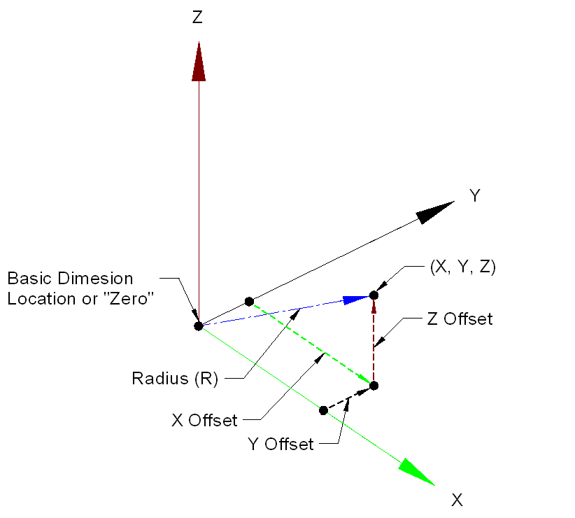
Cheers, Matt. The beauty of true position is the use of basic dimensions. You are specifying exactly where the perfect nominal feature should be then simply saying how far off of that perfect location your feature can go to be in spec. Torrent Logic Pro X 10.0.1. You would not put true position on a dimensional tolerance, because you are already specifying your position with your dimensions. The benefit of true position is that you are giving a clear nominal point, and by using datums, showing how the part should be measured and controlled. You also have the benefit with true position of having a circular tolerance zone, thus giving you a little more functional tolerance than with the square tolerance zone that exists with X and Y dimensions.
According to the ASME y14.5 True Position is the name given to the tolerance symbol labeled with the crosshair symbol. If the machining world you SHOULD say that the TRUE POSITION is a specific coordinate or that the POSITION tolerance is at 0.4. I think it is merely semantics though as if someone referred to a true position, you would understand that it is the exact point, but the true position tolerance would be the tolerance zone or range. If we are going by the ASME though, it appears to always refer to the tolerance as position and the specific location as the true position.
Great comment that got me thinking about this! Thank you so much for the kind words! For measuring certain types of call-outs you need special equipment. For instance, measuring the parallelism of a plate, only requires a granite slab and a dial gauge.
However if you are measuring the profile of a car hood, you will probably need more sophisticated equipment. A CMM is the ultimate measuring tool. Given enough time to measure, there really isn’t anything it cannot specify. Calipers on the other hand are really only good for measuring distance. You may be able to roughly measure some geometry, but not very accurately. In November we are releasing our GD&T Basics course. We go through each symbol and talk about what type of equipment is typically used in the industry to measure for it.
Check out our if you are interested in learning more. Thanks for the great question! I usually see True Position explained with hole positions and such. But how about for 2 flat surfaces in different areas? For example Datum A and Surface2 are supposed to be co-planar within 0.001″. But they do not touch, they are separated by other features. —————- One tricky thing about this is True Position does not tell you they are on the same plane, it just tells you Surface2 is only so far off of it’s nominal position, when compared to Datum A – no?